Keckler Week 6

Chapter 9

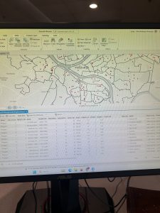
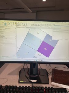
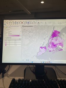
Starting with Chapter 9, this chapter emphasized the visual aspect of GIS to analyze spatial data. The first section started off well. I made the buffer zones representing the distance between public pools and local youth. Once I reached the second section in multiple-ring buffers, I began encountering some problems with the Spatial Join tool. When I would expand the “fields” section under the tool, the option to select an output field or merge tool were absent. I then encountered the same issue in the third tutorial that hindered my ability to fully complete the section. I also struggled with inputting the information for the gravity table. Moving to the fourth section, the fresh task was to use a tool to locate facilities. This section went well compared to the preceding two. As a pretty drastic shift from the work with public pool proximity was the cluster analysis of crime in the fifth and final tutorial. Thankfully, working with the GIS was smooth sailing and far less serious than the scatter of the serious crimes. 

Chapter 10

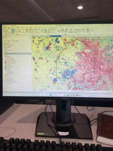
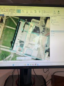
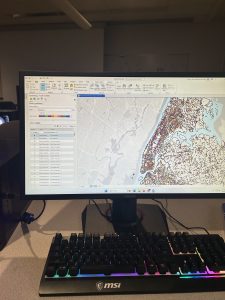
Next, was using Raster in Chapter 10. As per usual, I had a lot of weird troubles that I struggled to pinpoint the cause of. The first section started out alright, but then it took a turn for the worst. When I imported the raster dataset to become a file geodatabase, the program ran, but nothing was added to the contents pan. I could not figure out what the problem was because nothing popped up concerning anything incorrect on my information, but nothing changed or was added anywhere once it ran. Then, I had a bit of confusion about the Hillside Shade tool because there are three. However, I could not complete the section anyways because there was no NED_Pittsburgh that I could find in anything. Then, I could not change the symbology because I fumbled about every other preceding step. Continuing to the second tutorial of the chapter, the goal was to make a heat map. Thankfully, I could do this correctly, inputting all of the information correctly, selecting colors, and creating thresholds. For the final section of the chapter, the aim was to create a risk index model. As my pattern follows, things began orderly and grew unruly as I pushed forth through the tutorial. I struggled a bit with writing expressions properly, but I fixed everything to make it all work as intended. 

Chapter 11

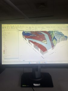
Finally, in Chapter 11, I fully realized the extent of my disdain for GIS on the desktop- or possibly just the school’s Wi-Fi. Using the 3D maps, I tried navigating past the command of pressing random buttons that correspond to movements. The navigation was abominable. Some of the keys would not move the map while others would have a five second delay before the map would move in the right direction. The additional capabilities that are expected from an ostensibly powerful system fall short of the expectations set and boasted in the book. The computer also froze for about ten minutes adding to my defeat. My qualms aside, the first two sections went swimmingly. I enjoyed the visual representation of trees on the map. Overall, everything for this section, though tedious, went about as expected. Drawing a bridge was a unique experience compared to what I did last semester in WebGIS, but my navigation quarrels still stand.

Keckler Week 5

Chapter 4

Chapter 4 was about working with databases. It was a bit funny to me, though, how once all of the additions were made to the Maricopa Tracts geodatabase then the directions said to delete it. It also made me mad, but I think that deleting the Maricopa Tracts geodatabase messed with something because there were no tracts to be found when I was trying to complete the second tutorial of the chapter. After that blunder, I moved on to the next section about attribute queries which are building on the SQLs from the previous chapters. This went smoothly since it was review from before. First you change the symbology to count, and that is followed by writing out expressions. Expression writing was followed by spatial joins which connect sums of a certain feature to polygons on the map; in this case, the counts were burglaries, and the polygons were neighborhood boundaries. The final section was about creating an attribute table for the neighborhood burglaries followed by creating a point layer. After the bumpy beginning, my proverbial DesktopGIS road smoothed out for the remainder of this chapter.

Chapter 5

Moving on to Chapter 5, the preface of the first tutorial boasted how many coordinate systems and map projections are in ArcGIS Pro. The first task was to look at a distorted map projection of the world, then, to change the coordinate system to Hammer-Aitoff in order to remedy the distortions. Moving from the entire world to just the United States, the second section required playing around with the coordinate systems of the US to show the country through the Albers equal-area projection. The next section continued with changing the projections and coordinate systems according to different map scales while manipulating some symbologies along the way. Getting through the projections led to working with shapefiles which will be pertinent for using the Delaware Data for the final exams. Everything with this went according to plan. Then, next was working with the US Census data. This section was a bit tedious, but I had a chance for redemption for my failed choropleth map from Chapter 2.

Chapter 6

Halfway through Part 2, Chapter 6 was a bummer. The chapter started off well. Working with the Pairwise Dissolve tool was alright, and the rest of the first two sections were well. The third tutorial threw me off. I could not find the merge tool. I searched for it- exactly how I searched for everything else up until then, but I could not find the tool. I was either fogged by my influenza or fogged by the frigid temperatures of the Science Center freezing my peeper over, but I could not find the tool. Moving on from the disappointment of the previous section, I was back to the Pairwise tools, and everything was fine. I fabricated some inputs and outputs then commanded statistics of the Manhattan Fire Company, and I proceeded to the sixth section. Staying in New York, the next section was about the neighborhoods in Brooklyn. First was working with attribute tables again, using the Union tool, performing calculations using GIS, and then making some queries. After this section, I encountered an issue using the Tabulate Intersection tool. After inputting the data, it was not working properly. I tried again and encountered the same result, so I moved on. 

Chapter 7

Moving and rotating the polygons in the first tutorial of Chapter 7 was fun. With that said, the process of saving the changed location of the polygons is inefficient. Each time I would click outside of the area to establish the new location of the polygon; it would move a bit. I feel like the apparent advanced nature of ArcGIS Pro would have a better way of keeping polygons in their proper positions- especially since they boast about the capabilities of their system. Besides my gripes, the movements were fun compared to the devastation of codes and the other minor things that have not worked properly for me. Exporting and moving the computer-aided design drawing was great; it was a nice reinforcement of what I had done before in the chapter, and it elaborated on other features in the program. The drawing looks like an overhead view of one of those spaceships from Star Wars, so that added an extra layer of whimsy to the GIS adventure.

Chapter 8

Chapter 8 was a heartbreaker. My geolocator code would not work. I tried to fix it, but it still would not work. This chapter was more difficult than the others for me because I kept messing up the inputs for the tools. I did manage to eventually make some of the tools work, but I ran into many roadblocks with the geocoding sections. I believe that I may have very bad luck, for I may not be meant to input simple data in ArcGIS Pro.

Keckler Week 4

Chapter 1

I had a significant learning curve with Chapter 1. It took a bit to figure out the user interface on the desktop compared to the WebGIS that I grew accustomed to last semester. Some new terms arose as well as some old terms were rehashed. A feature class is a grouping of common features that are represented using the same symbols, points, lines, and shapes- making feature classes somewhat similar to a point of interest but in a broader sense. I believe that now I understand what a Raster dataset is- more so than before. Raster data is image data whereas vector data concerns points, lines, and polygons just like feature classes. In my early learnings of the desktop software, I kept managing to remove my map and the contents tab, but I found out that there is a way to reset the contents tab. Though, I had to leave without saving to get the map back at least once. A problem I encountered throughout chapter one alongside the other chapters was the use of terms that I was presumed to already know such as ribbons, groups, and bounding boxes. With that aside, I have acquired the ability to better navigate through maps and data via zooming in and out, zooming to full extent, and properly utilizing bookmarks. Additionally, I have gained experience using Structured Query Language to easily locate the names of specific features. Building upon the claims of the Mitchell reading, I was employing the GIS software to perform statistical analyses using sum, mean, standard deviation, etc. In all of the learning I have done thus far, the most engaging part was going through the symbology of the symbols for the various features. Though, I could not find any such “Dialogue Launch” or “Active Symbols” tab when manipulating the labels and symbols of features. 

Chapter 2 

For Chapter 2, everything began smoothly with coloring the different areas. After that step, I had a lot of trouble finding the label class group on the ribbon for the next section of the tutorial, so I chose to move on. Otherwise, I did not have any trouble with using the popups. Then, once again, I was manipulating symbols- which I enjoy doing very much. When I moved on to making the Choropleth map, I encountered a lot of troubles that hindered my ability to perform everything properly. For some reason, I had an error come up every time I attempted to apply any settings under symbology, so I was virtually unable to complete the task. Moving past that, the next section went smoothly. I renamed the layer, changed the symbology, and that was all. Then, I had another issue with changing the symbology in the Female Headed Household feature. I was unable to change the method in the symbology to “manual interval.” Then, I had a lot of trouble locating the feature layer tab, but, as I acclimate to the system, I should eventually have less trouble navigating and location the different groups and layers. Following my pattern, the next section ran much more smoothly. I was working with symbology, and everything was great. Then, I encountered yet another roadblock. I could not locate anything labelled “beyond” or “current” in the visibility range group. There were only numbers where I found anything associated with visibility range, so I moved on.

Chapter 3

Chapter 3 was more geared towards my experience with WebGIS from last semester. By far, this chapter proceeded the most smoothly with no real issues inhibiting my ability to fully understand and complete the tutorials. For the first section, I transferred the maps to the sheet oriented for common viewership as well as creating the charts to understand and interpret the data of each map. After completing the sheet, I transferred the sheet and was reunited with my beloved WebGIS where I could set everything into precisely how it was meant to be. Then, I created the story map as I had many times before in 292. Next, I created the dashboard. I remember having trouble the last time I made a dashboard last semester, but this time went far better. With that said, when I made the table for the map, it ended up being on its own little separate section instead of being displayed with the map. I am unsure if that was intended, but it did not create any major discrepancies with showing all of the data in the finished product. At first, I thought the table I created disappeared into oblivion. Then, I found it in its own little area of the dashboard, so all was well. 

Keckler Week 3

Chapter 4

Often, GIS can be used to map density as a manner in which to clearly represent areas of highest concentration- such as with feral cats or oversized rats- for the purpose of seeking out various patterns. For example, oversized rat phenomena could be located in large urban centers due to the access of food, adaptations, etc, but maybe their oversized rats can be found in a rural area that is coincidentally near a nuclear waste site. Things such as the United States Census records data that can be used for density mapping for population, income, family size, etc. There are also two different options of representing density as density of features or feature values. As an example, density of features would show the areas with oversized rats while feature values would show the number of oversized rates in the areas. In addition, there are two manners of mapping density either by area or by surface, each with their own uses and drawbacks depending on the type of data you have and what you want to do with it. Some data can be best represented using individual points while other data is best represented using shades of color. For example, for relatively isolated incidents of the oversized rat phenomena, a dotted map could be used to examine relationships between rat outbreaks. However, if incidents of oversized rats become a prevalently explored and recorded phenomena, then a shaded map would become better suited to facilitate pattern recognition. GIS has the computing power to be able to make calculations with density data to generalize and present density data in a manner conducive for seeking out patterns within the data.

Chapter 5

When mapping a subject within the boundaries of an area, patterns within the area may be assessed or internal patterns can be compared to the patterns within other areas. Using feral cats as an example, feral cat information could be tracked with Delaware City’s Township and compared with other townships- within or outside of the county- to track patterns in where feral cats are the most prevalent. With that information, trap, neuter, vaccinate, and release programs can be sent out to places with the most need in order to manage cat populations. This information could also be used to find cats or kittens that could possibly be integrated into human households. The power of GIS allows users to use pre-established boundaries- i.e. counties, townships, zip codes, etc., or created boundaries to assess data depending on the intended span and use for the data. Determining whether the features are continuous or discrete is important when mapping data within. Discrete data would be the number of feral cat colonies whereas continuous data encompasses things such as elevation, vegetation types, temperatures, precipitation, etc. that are continuously present. GIS can be used for lists of features, the numbers of features, and for summaries, and GIS can be used to cut off certain data that is outside of a drawn boundary. From that point, there are three methods of finding what’s inside: drawing boundaries to show features outside and within, specifying an area, or to create a new layer that overlays the original. Each method, like the others, has its own uses depending on your goals for your data and analysis. Summaries for numerical data can also be implemented such as sum, mean, median, and standard deviation depending on the relevance of each for the best representation of data. To best express the need for managing feral cat populations within the city of Delaware,  I may want to use the sum of cats or average number of feral cats per square mile to stress the gravity of the problem. 

Chapter 6

As a counterpart to Chapter 5’s finding what’s inside is Chapter 6’s finding what’s nearby within a certain distance or range. An example of using range would be notifying people within a ten-mile radius of a colony of rabid bats. This can be used for distance but also cost through time, money, or effort. Maybe I wanted to let everyone know about the rabid bats that are a breezy five-minute walk away from their community park. With this knowledge of the proximity of rabid bats, I could better raise community awareness and issue warnings for pets, children, and nighttime park-dwellers to be wary of the rabid bats and remind them of the mortality rate of rabies. An alternative would be to determine the travelling pattern of my rabid bats to best alarm those in the path of rabidity. GIS has the power to draw my ten-mile bat radius and measure my five-minute walking time. Depending on my goals for rabid bat analysis, I could calculate distance if the Earth was flat, using the planar method, or incorporate the Earth’s curvature, using the geodesic method. The planar method would be ideal for a smaller area of interest- a city, county, or state, but the geodesic method would be necessary for any larger analyses- such as if my rabid bats spread from my little town to all contiguous US states. Just as with mapping what’s inside, data can be represented using lists, counts, or summaries depending on need. I would like a list of the addresses within a ten-mile radius of my rabid bat colony to ensure their awareness of the bats and to ensure that they have not yet gone rabid. In the aftermath, I would perhaps seek a count of the rabies cases in a post-rabid bat town, and perhaps I would seek statistics or graphs to easily review the impact of my rabid bats on pets, children, and those nighttime park-dwellers. The three manners of finding what’s nearby include straight-line distance- such as a ten-mile radius, distance or cost over a network- such as sidewalks, and cost over a surface- such as for the travel cost to reach my rabid bats.

Keckler Week 2

Chapter 1

I find it very intriguing how scientists are finding new ways to employ GIS aside from simply putting together maps alongside analyzing the space in and around those maps. Additionally, with the proliferation of remote sensing via drones and other contraptions, more spatial data in those harder to reach, ecologically sensitive, or other remote areas where new or different information can be recorded and applied in GIS software. 

With all of the details concerning how types of data and phenomena exist in GIS, I do wonder about the process to collect, record, and input the spatial data in order for it to be fit to analyze within the software. Is there a generalized set of data for most areas that can be accessed freely with the proper software– such as the Delaware Data from the Delaware County Auditor and co? Does the same thing exist for more precise topography around the globe? Also, who is accountable for updating data in areas lacking government use of mapping systems for tax purposes, etc.? 

Moving past that, there are the two types of representations for GIS features in vector and raster- which pique my interest in their differences. Vector models consist of XY coordinates, while raster models consist of expressions that somehow become continuous shapes. Each respective model takes up different amounts of shape and can be used for representing different types of data, but I wonder if there is another way to represent spatial data- especially since one model appears to be exponentially more complex than the other. Could there be any other way to represent continuous numeric data that would make doing so more accessible?

Chapter 2

One of the most critical aspects of mapping is that maps depict locations. Going a step further, is to use features within maps to analyze the various patterns within them in relation to locations and to each other. You could use these features to map out anything, really: bears, criminals, school zones, soybean fields, sewage leaks, etc. These features are given their own unique layer to be easily accessed and assessed. 

From that point, features are used for various purposes. If I wanted to assess the yield of soybeans, I would collect data- or review already collected data, compile and input information, then review. Once I know the yield of soybeans, I could compare previous yields and report to the Ohio Soybean Council or to the farmers directly and let them know how their soybeans are doing. Maybe there is also a pattern between the manner in which the soybeans are cultivated, such as with no-till or with limited chemical use, then I could analyze that information and communicate accordingly. Another possibility is that there is a relationship between soybean yield and location, then, I could record the coordinates of soybean fields in a particular area. I do wonder if the Ohio Soybean Council uses extensive GIS to strategically plant their monoculture fields. 

Shifting away from soybeans, GIS has a wide range of features that can be used to arrange, record, and track data. A major application of GIS mapping and analysis is for land-use and parcels, but there are many other possibilities- as established. GIS allows for easy assessment of distribution patterns from just taking a look at a zoomed-out map or through analyzing statistics for a statistically significant relationship.

Chapter 3

A highly important manner of GIS analysis is through mapping the most and least. An example of this would be mapping the amount of bubonic plague deaths per 10,000 people to detect hotspots where the bubonic plague is taking the most lives. There are three types of data: discrete, continuous, and data that is summarized by area. Discrete data represents bits of data including points of interest, lines, and areas. Meanwhile, continuous data represents entire areas or surfaces with continuous values- whereas discrete data is less encompassing. Summarized data represents shaded areas that are categorized- which can include discrete or continuous data.

The technicalities of GIS and map-making, in general, require an understanding of evaluating data and having the ability to apply that to a map. The many bits and pieces are the building blocks of GIS which allow users to visualize and express data. There are also many ways of quantitatively classifying data. Each means of classification, like the types of data, have their benefits and drawbacks that make them useful for different scenarios. Statistics play an important role in how many types of data within GIS are used and organized from standard deviation to outliers, and GIS has computing power to some extent for data classification. When creating a map, there are many options of the manner in which data is visually represented including symbols, colors, charts, contour lines, and 3D which, similarly to the ways of classifying data, have their pros and cons. The chapter provides a rudimentary guide for employing the various details that it discusses, but it is a bit difficult to retain every piece of information without something concrete to apply it to at the moment. There has been a lot of planning to shape GIS into what it is today.

Keckler Week 1

Hello! My name is Emily Keckler. I am from Marengo, Ohio and this is my first year at OWU. My major is Environmental Studies, but I am considering a double-major with Geography. As a fun fact about me, I love cats and eating my vegetables!

The use of GIS under real-life circumstances is an interdisciplinary tool that can range throughout different subjects depending on the goals of the user. The tool can be used in multiple different ways and is changing alongside technological developments. However, the initial rise of GIS was underscored as making maps on computers instead of realizing the technological potential of analysis using GIS data. It is very fascinating to read how GIS was being developed in many different areas leading to the proliferation of Environmental Research Systems Inc (ESRI) which has a stronghold on GIS technology- even today. I do wonder, though, about the apparent contention behind the initialization of GIS; it seems like it would drain a lot of energy to debate on its roots when GIS clearly has roots in multiple areas. Why argue about something so menial in the grand scheme of GIS? 

I also found the point about what the acronym “GIS” means to be particularly interesting. Some like GIS to be “Geographic Information Science” instead of “Systems” and vice versa. The differentiation seems arbitrary in that GIS- however it is defined- can be used in both ways that it is identified. Reading on, the lines between “science” and “systems” concerning GIS seemed to rapidly blur. It began to seem less like a meaningful differentiation and more like a power imbalance among what the technology is used for. It was also very comical that the section recognized the muddiness of the subject. Regardless, it seems that either “field” so-to-say can be employed to serve the role poorly distinguished through “GIScience” or “GISystems.”

Whichever way that it can be defined, GIS is critical to many functions in modern living. From transporting food from farms to grocery stores to delivering an Amazon package in two days, GIS can be used for almost anything.

As an application area I looked up “Vegetable Garden GIS Applications” on Google Scholar where I found an assessment of the possibility for the rooftops of Boston, Massachusetts to be used for agriculture (Saha, et al. 2017). Using geospatial technology, researchers mapped out the numerous rooftops of Boston to determine their viability to be made into green space for produce yields, carbon sequestration, etc. (Saha, et al. 2017).

https://doi.org/10.1016/j.landurbplan.2017.04.015

For a second application I searched “Banana Farm GIS Applications” and this led me to an article from the Agrarian University of Ecuador concerning using GIS to optimize the process of fertilizing banana crops for nutrition standards (Duque, 2022). The use of GIS in this process allows for accurate control and monitoring of banana crops, soil quality, pest control, etc. (Duque, 2022)

OptimizaciĂłn de la fertilizaciĂłn del cultivo de banano mediante el uso de herramientas SIG | Centrosur Agraria