Chapter – 1: 1-1. We made a map of Allegheny County, Pennsylvania. We started by highlighting Allegheny county, then we displayed the Urgent care clinics in the area, the FQHC clinics, Poverty risk area, population density, as well as rivers and Pittsburg for context. By looking at this map you can clearly see that the distance between hospitals increases as population decreases.
1-2. Zooming in and out of the map while vector data is being displayed can either mask or display it. Such as if you zoom in to a certain extent then vector data is no longer shown and if you zoom out it is redisplayed. This was shown when we turned off population density and selected poverty density instead, which is raster data and is displayed all the time regardless of magnification. To zoom in on a given area you can use the scroll wheel or you can press shift and draw a rectangle and it will zoom into that specific area on the map.
We then used SQL (structured query language) which is how we query tabular data. We used it to select McKees Rocks; this was done by selecting the Select by attribute button in the map tap, then Municipalities was selected under input rows, then in where we selected Name, then is equal to, lastly Mckees Rocks.
1-3. To look at attribute data for a class, you can right click on it in the contents pane, then select attribute table. When doing this we adjusted where the website was in the table. Data can also be sorted by right clicking on the column and sort either ascending or descending. Data can also be turned off in the display, this is done by opening the attribute table and clicking the menu button (3 stacked lines) this allows you to rearrange features or turn on/off their visibility. In this window you can also select a number of features, or to exclude features from a selection you can click the select button, click on an amount of featured data displayed on the map, then in the attribute table by selecting switch it will select all of the features besides the ones that were highlighted on the map.
Descriptive statistics can be generated using GIS. To do so in ARC, navigate to the analysis tab, click tools, expand toolboxes, analysis tools, and summary statistics.
1-4. To change the appearance of a symbol for a class such as a point, right click that class in the contents pane, click symbology, and then select the current symbol and the new symbol you would like to use. In this pane it is also possible to change the color of the symbol. Similar to symbology you can label and alter the labels of certain classes. We used municipality data, and labeled it. This is done so by right clicking a class and selecting label, then you can alter the text by selecting label properties.
We were also able to include data that was not previously in the contents pane by going to the catalog pane, opening the database, and dragging parks onto the map. This added a new class to the contents pane.
Chapter 2: 2-1. This chapter is about using maps to solve or investigate problems. This chapter looks at using different layers to best represent different data or variables, and this is achieved through using thematic maps. This is a type of map that has the subject/variable in full display and uses spatial data to give context to your subject.
To highlight land use, go to symbology for a given class and then select unique values for primary symbology. This then generates colors for each feature type, it is possible to select specific colors within this panel. This is done by clicking more and then formatting all symbols.
2-2. Using the map made in 2-1 we added general and detailed labels. When selecting a class in the contents panel it opens up 3 ribbons, one of which is titled Labeling and this allows you to select the type of field to use, in our case we used zone. Once you’re done making your selection click the large Label icon. To remove redundant labels, right click the layer you want, go to labeling properties, position, conflict resolution, remove duplicate labels, and then select all.
To remove pop-ups right click a class and then select disable pop-ups. To manage them go to configure pop-ups, double click the fields, deselect the Only Use Visible Fields and Arcade Expressions, along with the Display box, then you can select the features that you want displayed when you click on a polygon.
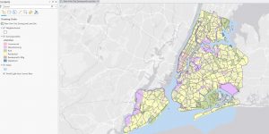
2.2 New York city land use map.
2-3. Some maps have a large number of features, such as point data. In cases where you want to filter what is being displayed, you can do so by going to the properties of that class, selecting Definition query, new definition query, then creating clauses for the features you would like displayed. We then used symbology to change the color and shape of the points for different food facility types. This makes it easy to distinguish between the different facilities and it also makes it easy for those with colorblindness to understand the map.
2-4. In this section we created a choropleth map which uses colors, and color values to visualize data. This method uses natural breaks as a default setting, but quantile classification can be a suitable alternative for a first time use since it’s easy to understand. To make a choropleth go to the symbology for the layer you want to use, select graduated colors, then your choice of field, your chosen method (quantile or natural break), your number of classes, and your choice of color scheme. You can also make a histogram to observe trends in the data. To convert a 2D to 3D you can do so by going to the view tap, in the view group section click convert and select to local scene. Then drag the layer you want converted to 3D to the top of the layers heading.
2-5. In this section we create graduated symbols to display data. This is done by changing the symbology to graduated symbols.
2-6. To use percentage data, create whatever symbology you want to use, then go to advanced symbology, format labels, then change category to percentage, percentage to number represents a fraction, and rounding decimal places to 0. To import the same symbology for a different layer, go to its symbology, go to options, then in the symbology layer, select the layer you are importing the symbology from. To compare layers easily, go to feature layer, and in the compare section click swipe, this allows you to click and drag the screen to reveal the layer underneath without having to turn layers on or off.
2-7. Dot density can be used to display more than one variable, however when using dot density be sure to use the same general hue for the colors so that it does not emphasize one variable over another. To make a dot density map go to symbology and choose dot density for the primary symbology. The dot value represents the amount of individuals 1 dot represents.
2-8. When working with visibility ranges it is important to note the ratio that you are using. For instance 1:50,000,000 is considered small scale despite the value being large, this is because 1/50,000,000 is a rather small number. Whereas a ratio of 1:24,000 is considered large scale since 1/24,000>1/50,000,000. To set visibility ranges, select your layer, then labeling at the top of the screen, then if you want it so that if you zoom out any further you wont see the label anymore set the minimum scale to current. This can be done for labels as well as entire feature layers, by repeating the same steps as before in the feature layer tab.
Chapter 3: 3-1. This chapter focuses on how to share maps with those who have limited experience with GIS or do not have access to Arcpro. This section is about how to make map layouts. To make a layout go to insert, and new layout. To add a map to the layout click map frame and select the map you would like to include. When resizing the maps in the layout, to get the map into full view there is a full extent function in the layout tab. When placing objects in a layout, it is helpful to create guides which can be made by right clicking the rules and selecting add guide, guides allow you to snap objects to them. To add a legend just click one of your maps in the layout to make it active, then click the legend button at the top of the screen. To add a chart right click your data frame, then create a chart, select the elements you need to create your chart, then click export to save it.
3-2. This section focuses on how to share/publish a map. To do so a map needs to have a base layer, and a property of the map needs to have been changed. To share a map, highlight the map layer in the contents pane, then under the share tab, select web map, then insert any information you need, click everyone for it to be a public map, then click share to publish it. To view your maps, go to arcgis.com, sign in, then go to contents, then my contents and your map will be displayed there. To modify the symbology in the web version, click the layers button, select your layer, then go to styles on the right side of the screen, this is where you can change the symbology. The same can be done for pop-ups by navigating to the pop-ups tab on the right side of the screen.
3-3. This section teaches you how to use ArcGIS story maps. This is essentially a better version of google sites. It allows you to create storyboards that include maps and charts. To start working on it insert a picture for the background at the top, by clicking the add cover button and selecting an image. Then you can start typing where it says “add your story”. To insert maps click on the plus button and add a sidecar then select your map.
3-4. This section teaches us how to make a dashboard, which is a map that has other forms of data accessible such as charts. To make a dashboard start by uploading a map to arc online. Then open the map and click open the dashboard. From here you can add a table by clicking the plus sign button that says “new element” then the middle of the map, and then by selecting table. To add a chart it is the same thing but select the type of chart you want to insert instead of a table. Dashboard – Bzdafka
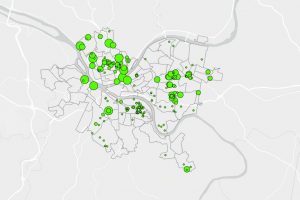
Map displaying age of 311 calls to have overgrowth debris removed. Size of point corresponds to age